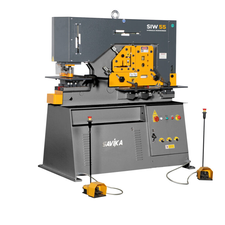
SIW SERIES
HYDRAULIC IRONWORKERS
The SIW machine is supplied with standard tooling including repetition support tables at punch, shear and notch stations. All five work stations are equipped with easily adjustable hold downs to safely control each operation. Comprehensive safety guards are fitted as standard on all work stations.
The SIW Range are twin operated machines with the hydraulic system activated by two shielded foot controls, one operating the punch and cylinder, the other operating the shear end cylinder. The shear cylinder provides the power to the three shearing and the notch stations.
The system gives accurate power inching at all five work stations and allows the machine to be stopped at any position giving safe and accurate tool setting and work positioning. Centralised lubrication is metered by oneshot system, being only one feature of the low maintenance requirements. A 1M touch and cut ruled length stop and an integrated LED lighting system are supplied as standard equipment.
FEATURES
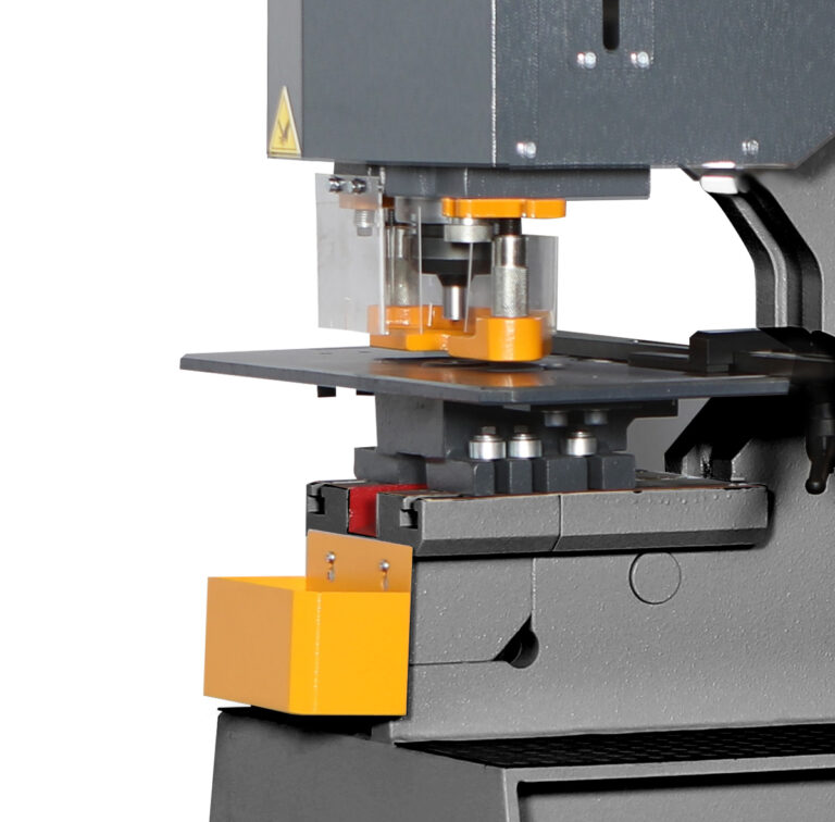
- PUNCH STATION
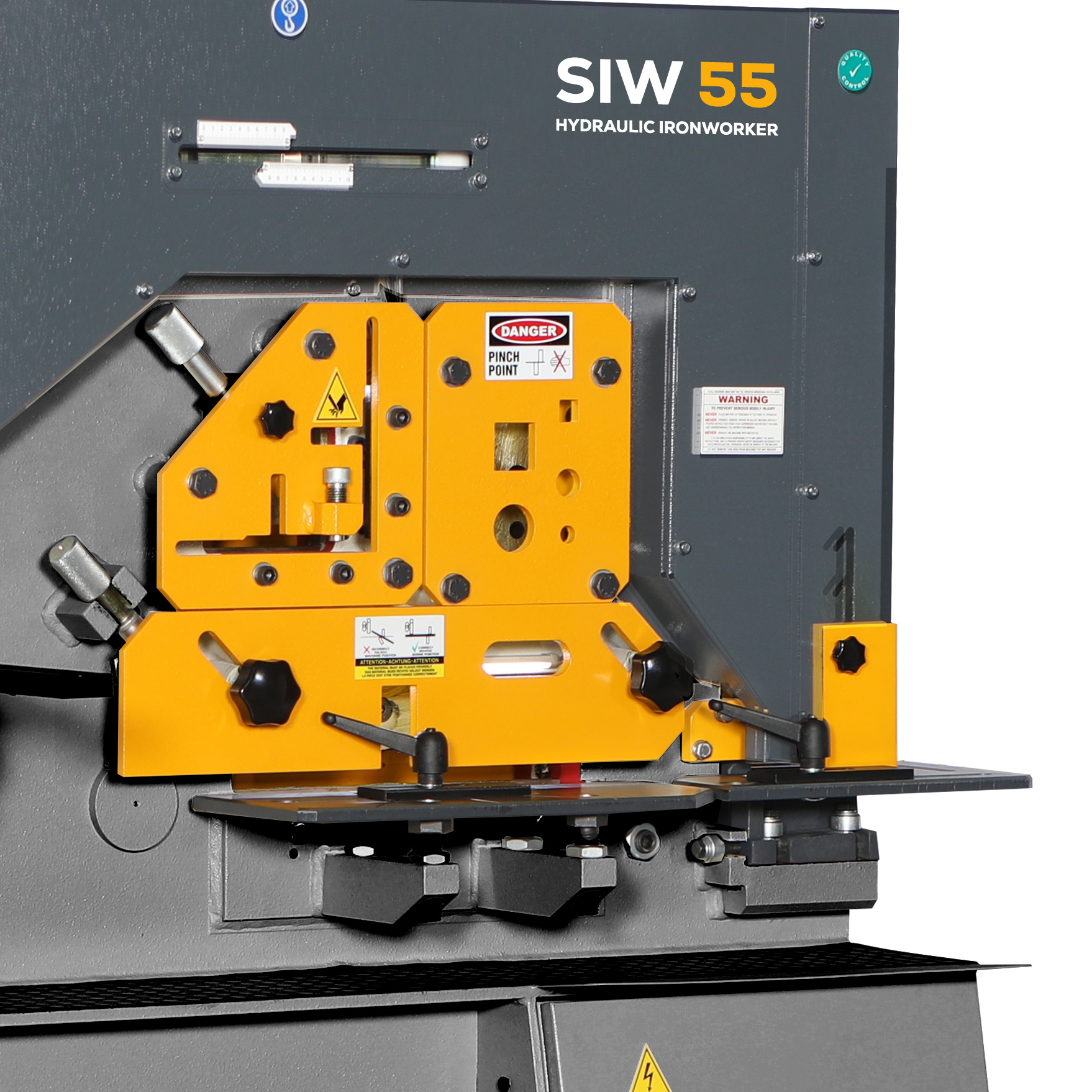
Easy tool change system and swing away stripper with fast manual adjustment ensure a quick setup. - ANGLE STATION
This station provides large capacity angle cutting at 90º and 45º. Angles between 45º and 90º can be achieved by first cutting at 90º and then flange trimming to the required angle in the shearing station. - SECTION CUTTING STATION
The machines are fitted as standard with blades for cutting round and square bars. With extra equipment, the machines are able to cut, in this aperture, channel, joist, T-sections and many other special profiles. - NOTCHING STATION
The notching station is fitted with a table with adjustable back stops allowing repetitive positioning. - SHEARING STATION
The shearing unit is fitted with a simple robust holddown which is adjustable to any thickness of material within the cutting capacity of the machine. The shear feed table with adjustable guides is fitted to allow accurate feeding of materials. The guide can be adjusted to allow mitre cutting up to 45º for flat bars or to trim the flanges of angle. - AUTO CROP RULED LENGTH STOP
Standard 1m stop with automatic shearing bypassing the foot switch for production applications. Can be used on all shear stations. Available in 2m and 3m options.
OPTIONS for SIW IRONWORKERS
- Bar bending attachment (pressbrake tool)
- Various sizes of Punching Dies and tools
- Possible MUBEA, GEKA, Kingsland Adapter Rings (Default Setting for Kingsland Type)
- Cropping blades for channel and other profiles
- Vee notch unit instead of standard rectangular notch unit
TECHNICAL DATA
| MODEL | SIW 65 | SIW 85 | SIW 115 | |
| Punching | Capacity Tons –> | 65 | 85 | 115 |
| Diameter X Maximum Thickness | mm | 26 x 20 | 33 x 20 | 35 x 25 |
| Maximum Diameter X Thickness | mm | 57 x 10 | 57 x 12 | 57 x 16 |
| Stroke Length | mm | 55 | 80 | 80 |
| Throat Depth | mm | 305 | 355 | 355 |
| Largest Hole Diameter – Standard | mm | 38 | 57 | 57 |
| Largest Hole Diameter – Optional | mm | 160 | 160 | 225 |
| Shearing | ||||
| Flat Bar – Width X Maximum Thickness | mm | 300 x 20 | 380 x 20 | 380 x 25 |
| Flat Bar – Maximum Width X Thickness | mm | 375 x 15 | 480 x 15 | 600 x 15 |
| Angle Flange Trim – Max 45º | mm | 100 x 15 | 120 x 15 | 120 x 15 |
| Angle Cutting | ||||
| 90º Cut | mm | 130 x 13 | 150 x 15 | 150 x 18 |
| 45º Mitre (True Int./Ext.) | mm | 70 x 10 | 80 x 8 | 80 x 10 |
| Section Cutting | ||||
| Round/Square | mm | 45 | 50 | 55 |
| Channel/Beam – (Optional) | mm | 120 x 58 | 160 x 74 | 200 x 100 |
| Tee – (Optional) | mm | 90 x 11 | 100 x 11 | 120 x 12 |
| Notching | ||||
| Material Thickness | mm | 10 | 13 | 13 |
| Width – Rectangle | mm | 45 | 52 | 60 |
| Depth – Rectangle | mm | 90 | 100 | 100 |
| Depth – Vee | mm | 60 | 70 | 80 |
| Tube Notch (Optional) | ||||
| Maximum Outside Diameter | mm | 83 | 108 | 108 |
| Bending (Optional) | ||||
| Bar Bending – Maximum Capacities | mm | 250 x 13 | 250 x 20 | 250 x 22 |
| Sheet Bending – Maximum Capacities | mm | 500 x 3 | 500 x 3 | 700 x 3 |
| Punching At Notch Station (Optional) | ||||
| Throat Depth | mm | 125 | 125 | 125 |
| Maximum Capacity – | ||||
| Diameter X Thickness | mm | 38 x 8 | 38 x 10 | 38 x 12 |
| Technical Data | ||||
| Motor Power | kW | 5.5 | 7.5 | 11 |
| Nett Weight | kg | 1620 | 2430 | 3080 |
| Length | mm | 1700 | 1920 | 2040 |
| Width | mm | 710 | 790 | 800 |
| Height | mm | 1800 | 1910 | 2030 |